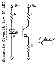
So, I was turning current on and off by breaking the beam – now to connect to the Arduino.
And at this point I realized I didn’t know exactly how to!
Therefore, it was time to break out the switch tutorial and start from there. I understood how a switch connected between a digital pin and the +5volts would be detectable, but the ground wire and resistors were a bit confusing in the example (to make matters worse, the tutorial omits a resistor between +5v and the pin, which I think risks a high current situation, but I’m not sure).
In any case, their switch circuit was simple: +5v goes to one side, the other side goes to pin 2, and I run the example sketch “Button” to test. The odd thing was the 10k resistor connecting the pin side of the switch to ground. To make a long story short, the idea is that when the switch is closed (on), +5v goes to the pin, exactly as expected. But if the switch is open (off), there’s no circuit, and the pin ‘floats’ in an indeterminate state (apparently due to signals inside the chip affecting it). So the ground and pulldown resistor forces the pin to a known state when off. Being such a high value, the resistor doesn’t interfere with the switch, yet gives us a decent ‘off’ signal of zero.
However, when I ran the button sketch, nothing. I should have the LED on the Arduino display immediately, and only go off when I interrupted the infrared beam.  But nothing at all.In any case, once I understood the need for the ground and resistor, I tried to hook it up to the Arduino. I kept the infrared LED circuit separate, since I didn’t want to burden the Arduino power supply (which was the USB). The transistor was powered by +5v from the Arduino, through a small 180ohm resistor; and the other side I connected to pin 2, as well as ground (but through a 100k resistor).
So I tried something else – I hooked the pin line not to pin 2, but to analog pin 0. This way, I figured I could see if there was any reading whatsoever. And to catch the value, I used the AnalogReadSerial sketch instead.
When run, I got a treat – a steady display of the value 200 (more or less) scrolled down the screen. And when I broke the light beam, it went to zero.
So, I had my detector, as long as I was willing to use an analog pin to detect it. Time to relax, as my job was done. The Arduino worked successfully with my photointerrupteur.
However, I wanted more – I wanted a DIGITAL detection…
(Check this next article for how I solved the digital problem, and part 3 for the final result)

Brilliant, thanks for taking the time to write this up. I was looking for exactly this having salvaged a couple of slotted optical sensors from an old printer.
hi,
First, thanks for tutorial, do i have an issue about plugging photo interrupter on arduino board 3.3v.
Most of photo interrupter are 5v. How can i plug it to 3.3v arduino board please.
Thanks
Did you ever get this working? I’m trying to do the same thing with a raspberry pi but I’ve got the additional problem of trying to step it down to 3.3V for the signal. Any luck!? Thanks!
Re this circuit, I’ve done the following using just an Arduino and a H21A6 from RapidOnline:
The spec for the R21A says that the LED requires 1.2v and draws 50mA. This means if we are using the Arduino to supply bower (5v) we need an 82ohm resistor, I used 100.
Pin 1 now goes to VCC (5volts) from the Arduino and pin 2 goes via the 100 Ohm resistor to ground.
Pin 3, bottom right if Pin 1 is top left, goes to the Arduino and Pin 4 goes to ground.
That’s it, all you need to do now is set the input pin on the Arduino as INPUT_PULLUP, and then you can read the status with DigitalRead which will return a HIGH or LOW state.
Enjoy!!
Just add threshold detection transitor or Opamp circuit after the optical sensor circuit, and you will have your digital signal that you can then send to a digital input.
Hi sir, I am using OPL560 photo transistor, it has 3 leads 1. ground 2. output 3. Vcc. now resistor has to connect to which terminal either 2 or 1.
Can We use Optical Sensor H92B4 Instead of Optical Sensor A9121..? Is that some Similarity between the two?
I am now not certain the place you’re getting your info, however good topic. I needs to spend some time learning more or figuring out more. Thank you for magnificent info I was on the lookout for this information for my mission.
I really like your writing style, good information, thankyou for posting D.