
When I read Graeme McCreath’s book “Politics of Blindness” earlier this year, I was appalled at what the CNIB was doing. As a sighted person, I naturally assumed they were taking good care of the blind, helping and assisting them in any way possible to enhance their lives, and maximize their contribution to society. I was wrong – very wrong (I won’t spoil the book for you – but please read it as soon as possible, or better yet, buy your own copy, and copies for your friends – it’s that eye-opening).
After reading that book, I realized I wanted to do something directly. So, consulting with local blind people (including Graeme himself), I decided to start with a Braille Display.
Typically, if a blind person wanted tactile Braille from anything digital (computer display, website, etc.) it needed to be converted in to six individual ‘dots’ per character, using small pins that were raised or lowered so as to create the appropriate letter (or combination, which is the case with Grade 2 Braille). This three by two grid of dots is the Blind person’s character set:
However, Braille display devices run around $7000 – well out of range of most blind people. Yet with a device like this, doors open wide; for example, all the content of the Internet can be read in the comfort of your home; writing and interaction becomes much easier, and waiting for huge Braille volumes in the mail is a thing of the past.
Braille provides the most reliable communication medium for a Blind person to access the printed word, and therefore denying it (or making it so expensive as to effectively deny it) is an injustice. According to one study, 56% of those who read Braille were employed, versus 23% for those who could not. Obviously, lack of Braille instruction is significant. The fact is, for blind people, Braille is a right, not a privilege. And for that reason I designed a Braille Reader to bridge the gap:
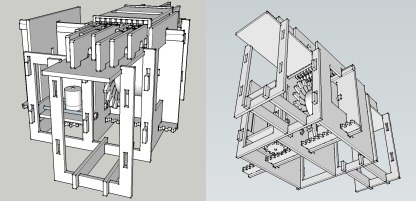
This Refreshable Braille Display (called ‘Audrey’, after my mother) takes in computer data and displays it on a small window in the center. This prototype is only five characters; it’s a proof of concept to get the programming, alignment and so forth ironed out.
To understand how it works, consider a single Braille character of two columns of three dots each. Any of these six dots can be either raised, or not; computer programmers will likely catch on right away that means 2 to the power of 6, or 64, possible patterns are available. If we were to mold all 64 patterns onto a long stick, and then move the stick forwards and backwards so that the appropriate character showed through a tactile window, we’d have a simple mechanical Braille display.
Of course, there’s a problem – such a stick would need to be long – at about 1/2 inch per character height, you’d need a stick 32 inches long! Also, the time to move the stick back and forth with a motor would be very time consuming. So as a compromise, this device uses two sticks per character, one each for the left and right columns:
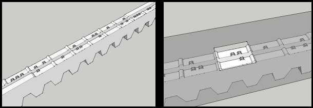
The result is that eight possible patterns per stick is enough to display all 64 possible Braille characters, in a smaller package, and with faster update speed.
From there, the design next requires a motor to move each stick. Of course, it’s not practical to use one motor for each stick or pin, so we use a single motor for all, with a second motor to move the first from pin to pin (much like a printer moves the active head across a piece of paper). This cutaway shows the mechanical parts in better details:
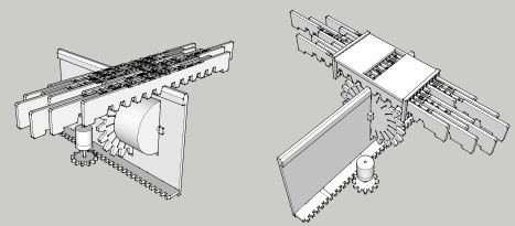
To finish off, the rest is straightforward: using the Open Source Arduino microcontroller running a monitor program, the Braille Display receives serial data from the computer, translates it into movement and position data, and then moves each rod or stick to the appropriate character position. A motor controller board, additional serial port, and assorted switches and wiring, is about all that is needed to complete the design.
The result is a low cost Braille display – in fact, I estimate a 40 character display can be made for under $200, significantly less than the multi-thousand dollar devices out there today. And while it won’t have all the features of the top of the line model, it will enable those who could never afford a Braille display to actually have one of their own.
In fact, the motivation behind my design has always been ultra-low cost; using two motors for instance, instead of multiple ones reduces the cost considerably. Also, the design is currently adapted for use with a laser cutter, which means that the parts could also be cut out of various materials with hand tools. And the hardware is minimal; with Arduino devices selling for $20-$30 dollars on eBay (and that of course is with sellers still making a profit), even someone in a third world country should have access to the components to build this device cheaply.
Additionally, my goal is to Open Source every part of this device. Open Source solves several problems; unlike proprietary knowledge, this is available to anyone to edit, change, and hopefully, improve. It means ideas can spread faster, with no proprietary ‘locks’ to restrict knowledge. It is immune to accidents; should I for any reason leave off the project, someone else can continue. And with more minds able to look at the issue, the chances for solutions becomes exponentially greater. As Linus Torvalds of Linux fame pithly observed, “Given enough eyeballs, all bugs are shallow”. Opening the hardware and software to this device ensures that problems are visible and are dispensed with quickly.
I do not consider this the ultimate answer to low-cost Braille display – far from it. It is a first small step. However. it’s 2011 – isn’t it time someone took a step forward? It is my hope that from this point on, others will take bigger and more confident steps, with the result that the true beneficiaries, those that are blind, obtain better and better products at lower and lower prices.
One day soon, I imagine a young child in rural India finally being able to take in all the text of the Internet through a Braille Display – if we can provide her with the opportunity, it’ll have been well worth it.
right now, your minimum stick length would be about 4 inches, with eight possible positions for the sticks (24 dots per column). This would put your minimum depth (front to back) of the device at 8+ inches. I had an idea to have an 8 position stick but only use 10 dots per column.
*=dot – = no dot
stick > | * – * * * – – – * – |
Take any 3 consecutive dots or spaces along this stick, and you can represent all 8 positions of a single column of your braille character. Thinking about it in binary, the first 3 would be 5, then 3, 7,6,4,0,1,2.
This would make the sticks about 2 inches long (you have to add a bit at each end, to keep it in track), making the minimum depth 4+ inches. Please email me and let me know if you got this. I hope i explained it clearly. if not, i can try a different way. thanks. 🙂
Yes Shane, that would shorten it, and you explained it clearly. Overlapping the possible patterns would make the display much smaller.
I had thought of a similar design awhile back when I was planning on 16 positions (4×2 Braille dot pattern instead of 3×2). For instance, this pattern of 19 bits represents all 16 possible 4-bit values, depending on where you start in the pattern:
1100100001111010110
(Later edit: note that a circular disk only needs the first 16 bits, since the pattern can wrap around; however, a rod version needs those extra 3 bits to complete the last 3 patterns. Also, the sequence as a whole is reversible, allowing you to count out all 16 numbers by moving clockwise OR counterclockwise on the disk).
However, the extra complications of motor control and managing each position (in the 3 bit case, you still need to manage 8 positions, but now in under 2″, making for a very small gear track) made the longer stick seem a better first option. As well, I wanted spacing between each pattern (standard Braille has space above/below a character), so I abandoned it. It might reappear in a later model, however, so thanks for the input!
also, if you designed the gears so that the teeth had a tapered or rounded cross section, the drive gears (also tapered) engaging them would be a bit more forgiving when engaging, but could still be held precisely in place by the lock bar/motor dolly.
if you curved the sticks into a partial cylinder, you could get it into an even shallower frame.
lol, was brainstorming, and missed your reply. 😛
a small lock lever that is pushed up by the motor frame as it passes would reduce the minimum width of the device (but increase the complexity somewhat)
you should really put this on youtube, where people can see it. there are plenty of helpful people out there who love challenges like this. Maybe, after you iron out the bugs, put it up as a kickstarter project.
just a suggestion.
🙂
OR, present it to the MAKE magazine people as a challenge. those people LOVE to find uses for the arduino.
Shane – thanks very much for your comments – to answer some of them: the tapering is a good idea – the reason it’s not shown here is this design is for a laser cutter, and all edges are 90 degrees to the main item’s surface because of the laser angle when cutting – however, I plan to smooth a few edges. The goal for this is a prototype only, and to get the kinks out of it. Eventually I want to cast the rods in plastic so I can add rounding, contours, etc, and bend metal sheeting for much of the internals. As for the lock lever, it’s a good idea, but as you mentioned, complexity is the issue – however, the left/right rod grows with the # of rods/characters used, so a large display will likely need another solution than the current one; for example, a flexible circular chain that curves under the motor, but remains up top to lock the rods in position. Another option is some form of telescoping rod pair, with the motor ‘pushing’ and ‘pulling’ them open/closed as it moves along. As for the curved display, it will save space – in fact, my original ideas were for a solenoid version and a circular disk version; however, in both cases, the complexity is much more than this design, and I felt a good first goal was keep it simple, and work on faster/better/stronger later. As for Youtube/kickstarter, my eventual plan is to put a motion video on youtube and run a IndieGoGo project (Kickstarter is a problem for us Canadians). Unfortunately, money, time, equipment issues, and health has been slowing the project down, but I’m optimistic over the next two weeks…
the telescoping rod idea is brilliant. also something like this:
http://www.engadget.com/2004/06/08/rotating-text-to-braille-converter/
with a circular reading surface would eliminate the width problem, but reintroduce the depth problem. :
I also found this:
http://www.vidyavrikshah.org/NWPB-2.htm
it uses your wheel design and carriage. and the disks appear to be modular.
sorry, I also found this: which (among other things) suggests a belt, embossed with dots.
http://www.users.waitrose.com/~stveorg/TactDisp.htm
If I understand the rotating disk one, it generates a raised character as it moves around – if so, I saw a patent for that. Odd how we haven’t seen much of it since 2004. Another reader also pointed out the NATESAN display (he had been working on it), which looks interesting; also, the belt idea looks very compact, which is nice. One issue with these is that they require a driving source at each character (or 1/2 character) display – which is a lot of motors. But if you use a single motor, moving it along the row and then engaging/disengaging with each disk is problematic. In fact, when I was working on the original disk idea, I was using rack and pinion gears, with the motor moving amongst them and moving the rack, which moved the disk. Then one day I realized if I printed the characters on the rack gear, I could get rid of the disks! Hence the current design.
Excellent project! I commend you on getting this far. My suggestion would be to create some of your parts using a 3D printer. That way you could create your semi wheels with the dots right on the arc’s.
Since our local hackerspace has a 3D printer project at the moment, I’d like to see this project fully documented so that we can make a few of these for our local school for the blind.
Please let me know how I may be able to help..
Thank you for your kind words. I agree that the rods need to be done in 3D – the laser cutting was just the simplest way to do a prototype right now. In fact, the design is in Sketchup in 3D, so you could test it out on a single print and let me know what you think, or if it needs tweaking. And as soon as I have a forty dot display ,rest assured I’ll be posting it – you can keep abreast of the project at the main page:
https://www.utopiamechanicus.com/braille-display-project/
Cool device!
It has often amazed me that braille print and display technology does not appear to have developed at all in the last forty years.
I sometimes toy with the idea of a printer, another badly needed piece of machinery. Your idea seems to solve several problems I’ve had with the printing head. Printers tend to be manufactured small, expensive and with peculiar interfaces that become obsolete long before they are delivered. Most of my friends have 90’s rs232 versions!runs and
How about a USB-connected ASCII-printer?
I also figure braille could benefit from being printed on tape rather than sheets since this could make it more manageable than the huge and heavy sheets people have to carry to and from meetings (that is IF the bloody things are ever printed on time).
Thanks! I was amazed too by how little technology has updated for Braille devices over the years. Hopefully, people will be able to improve this one and then everyone will benefit. I like the printer tape idea – I wonder if Blind people would find that easy to use, because it really would make for a simple device (kind of like those dynatape embossers…) As for the interface, I’m working with the Arduino, which uses USB – one side benefit is that the code for the printer could be the start of interface code for any Arduino/Braille project, once done.
By using three motors, the update rate could be doubled.
Two motors operate the left and right half digits, and the third moves the motor pair to select a digit.
Not too much additional complexity…
You might consider using stepper motors instead. Recent work with conventional hobbyist RC servos suggests that over the long term, repeatable positioning suffers with time / wear / temperature / other.
Salvage steppers from dead CD ROM drives. Or modify the optical assembly (with its stepper and slide rails) to carry the half digit motors – it already moves linearly. A dead flatbed scanner or inkjet printer might also serve as a good source for larger sub-assemblies.
I agree, more motors would add real benefit with little extra effort – after all, the code for moving one motor should easily duplicate for a second one. As for the motors, although I don’t mention it here, I am using steppers – the need for precise positioning made me settle on them earlier on – and the Arduino code for steppers, and drivers board, like the LadyAda motor shield, are quite good.
I’m just thinking out loud here but wouldn’t it be easier to create the display with little metal rods and small solenoids?
Unfortunately, Braille characters are rather small, so setting up and managing solenoids is difficult (and power hungry) – I explain why I went with this design first here:
https://www.utopiamechanicus.com/697/why-this-design/
Just a thought but have you seen those date stampers? They have rubber belts with multiple characters on them… If they were Braille and raised, you could have a similar system for selecting and changing the characters but it would be simpler to introduce multiple lines of text, if you for instance put a series of black marks on the inside as an encoder of sorts odd even odd even or similar with an optical reflector gate to read the position it might be able to be made faster. maybe a shift register and counter arrangement for each one or maybe set them in pairs like the old counters from tape players to make encoding easier. if I had lots of free time and money I would give this a go (:
Yes, a belt/wheel would make things much more compact, and allow multiple lines of text. In fact, this idea is very similar to one I and N.Krishnaswamy independently came up with for circular disks (not necessarily made of rubber) – you can see his design online at http://www.vidyavrikshah.org/NWPB-2.htm
However, I moved from disks to rods due to spacing/complexity issues, which I explain in https://www.utopiamechanicus.com/697/why-this-design/
I love mechanics and automation but motors and sprockets are difficult, complex and expensive, not to mention slow in this application. I don’t know anything about Braille reading techniques but I would find confusing the sliders moving from character to character. On the other end, small solenoids are cheap to build and easy to control and could be bundled together and drive short pieces of cable to show up through a “reading plate” with a complete line of information. Think about a dot printer’s head.
Since the amount of movement to the dot become perceptible is so little, you could also use some “muscle wire” which would make things easier.
To help show the sliders in action I wrote a small interactive display at this post:
https://www.utopiamechanicus.com/736/braile-display-dot-rack-design/
Unfortunately, solenoid technology has problems: power issues and cleaning issues (dirt in the pins) are two major ones. As for muscle wire, the heating and cooling in such a small space is problematic: and again, cleaning of the pins is an issue. However, if you yourself can come up with a design for a solenoid or muscle wire that solves these issues, I would be more than happy to incorporate it into an Open Source design!
I am a blind computer user and came across this project while searching on Google. I will continue to watch this project with alot of interest.
Good Idea
I am going to design this device with 8 charcters , but how I can use only one Arduino,
Also I find some difficulites in the computer programme and in the Arduino Programming and type.
Please if you have any documents related to my questions , send it to my email
Thank you ..
Using a driver board like the Adafruit one, you can control 2 steppers at a time with a single Arduino, which is all you need for the display. As for software/docs, I’m posting them as I finish them – stay tuned!