
 I once watched a science program where a blind person walked an obstacle course. He did it by making a clicking sound and detecting objects from the sound reflected back – in effect, ‘seeing’ the path with sound.
While few sighted people are that incredibly skilled, you can get a feel for ‘seeing with sound’ using a simple sonar range finder and an Arduino. It’s not just a toy (although playing tag in a dark room with a few of these might be interesting), but a serious tool to explore assistive technology. By ticking rapidly when you’re close to something, and less so when you’re farther away, it’s a simple device to audibly ‘map out’ an area.
My goals for this project were simple:
- It had to be easy to make. I’m not an electrical engineer, and I wanted the project to be easy to put together for me or anyone else. Low part count and simple assembly were key for me, not only to make my life easier, but to encourage others to build one (or two, or a dozen).
- It had to be simple to use. My first designs (discussed here, here and here) included a ‘flashlight’ with sine wave audio, a vibrating motor, plus the ticking sound. In the end, the output choices made the project too complicated. Instead, by starting simple there’s room to grow, yet we have a working device right now: A ticking sound for range, and one button to turn on and off.
- It had to be flexible. In talking to others, I realized many people want to help the blind, and a device like this had to be flexible enough to use it in a variety of situations. I designed the case to be small but tough, and included slots to fit straps through. Using them, you could tie this device to a cane, wear it on your head or hand, or even mount it somewhere permanently (where it becomes an audible motion detector).
- It had to be low cost. Although I’ve worked with (and like) the MaxBotix line of sensors, they were too expensive for this project. Using the popular HC-SR04 sensor and the Arduino Pro Mini, I can source the parts on eBay and build one for well under $10.
So to get started, let’s look at the circuit.
Design Part 1: The Circuit
I’m a big fan of the Pro Mini, since you have a low cost device with all the power of the Arduino, but a cost of less than $5 (under $3 sometimes on eBay). It does need an external USB port, unlike most other Arduinos, but once you’ve gotten used to that (no doubt with the help of articles like this one), you’ll find it straightforward to work with. However, if you prefer, other devices, like the Nano, can also be used.
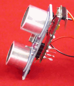 I probably broke a lot of circuit-building rules in this design, but I wanted a compact product, and the result is a simple circuit to wire up. For example, if you look at the HC-SR04, you’ll notice the four bent pins exactly match the 0.1” spacing on the Pro Mini. So why not bend them straight and solder them directly to the Pro?
It worked fine, but meant I had to run the whole device from four Arduino pins, rather than two signal pins and +5v/Ground. No problem: In the Arduino world, power is available via the digital pins by first making two of them outputs, and then setting each HIGH or LOW for the +5v and 0v (ground) respectively. In code, it would be something like this:
pinMode(PIN_SONAR_VCC, OUTPUT);
digitalWrite(PIN_SONAR_VCC, HIGH);
pinMode(PIN_SONAR_GND, OUTPUT);
digitalWrite(PIN_SONAR_GND, LOW);
Of course, you have to be careful, since no pin should source or sink above 40 mA, and many recommend a limit of 20 mA for safety. In this case, the HC-SR04 uses 15 mA maximum, so it’s not problem. Plus, it makes wiring easier!
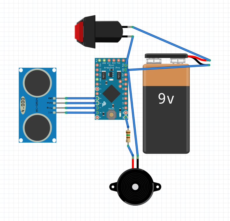
click to enlarge
Some may feel you can go higher for a device with intermittent current like this (since it clicks infrequently, the average continuous current is actually much lower than 30 mA), but I didn’t want to take a chance. The resulting volume is quite fine. Alternately, you could wire in a potentiometer to get a volume control, as long as the minimum resistance never goes too low.
Finally, there is the power switch, which is simply a latching on/offswitch in series with the positive side of the battery and the RAW input on the Mini.
One warning about the circuit: Recheck your work often, and try to test as much as possible before soldering. When I put mine together, I placed a resistor in the wrong hole, and mounted a defective sonar unit. Fixing those glitches once soldered was no fun, and would have been easier if I tested everything ‘one more time’ beforehand. Definitely for the first project, consider breadboarding it first, and getting two of every part so you can look at the breadboard as you assemble the second one, instead of scavenging them for the device and breaking up the only working prototype!
Design Part 2: The Programming
The code to run this basic system is here (or downloadable as sketch_sonareye.zip):
/* SonarEye Geiger Counter Style Ranging Copyright © 2012-14 - David PankhurstSonarEye: An Open Source Way To ‘See’ With Audio Using The Arduino*/ #include <avr/pgmspace.h> // set to -1 to avoid using it and extra power #define PIN_LED (-1) // sonar device pins - can be changed #define PIN_SONAR_VCC (8) #define PIN_SONAR_TRIGGER (PIN_SONAR_VCC-1) #define PIN_SONAR_ECHO (PIN_SONAR_VCC-2) #define PIN_SONAR_GND (PIN_SONAR_VCC-3) //-------------------------------------------------- // audio pin - cannot be changed as tied to interrupt #define PIN_AUDIO (10) volatile unsigned char gRate=255; #define PING_USEC_MAX (20000) //-------------------------------------------------- void setup() { // for now... if (PIN_LED>=0) pinMode(PIN_LED, OUTPUT); pinMode(PIN_AUDIO, OUTPUT); pinMode(PIN_SONAR_VCC, OUTPUT); pinMode(PIN_SONAR_TRIGGER, OUTPUT); pinMode(PIN_SONAR_GND, OUTPUT); digitalWrite(PIN_SONAR_VCC, HIGH); digitalWrite(PIN_SONAR_GND, LOW); cli(); TCCR1A = 0; TCCR1B = 0; OCR1A =16384; TCCR1B |= (1 << WGM12); TCCR1B |= (1 << CS10); TIMSK1 |= (1 << OCIE1A); sei(); } //-------------------------------------------------- void loop() { long value=0, pwr=0; while (1) { if (0<=(value=PingIt())) { gRate=1+value*254/PING_USEC_MAX; } } } //-------------------------------------------------- ISR(TIMER1_COMPA_vect) { static int waitCount=-2; static bool signalOn=false; if (--waitCount>=0) return; if (signalOn) { digitalWrite(PIN_AUDIO, LOW); if (PIN_LED>=0) digitalWrite(PIN_LED, LOW); waitCount=gRate+10; } else { digitalWrite(PIN_AUDIO, HIGH); if (PIN_LED>=0) digitalWrite(PIN_LED, HIGH); waitCount=12; } signalOn=!signalOn; } //-------------------------------------------------- long PingIt() { static unsigned long tickStart=0; unsigned long tick=micros(); if ( tick-tickStart<70000) return -1; tickStart=tick; digitalWrite(PIN_SONAR_TRIGGER, LOW); delayMicroseconds(2); digitalWrite(PIN_SONAR_TRIGGER, HIGH); delayMicroseconds(10); digitalWrite(PIN_SONAR_TRIGGER, LOW); delayMicroseconds(2); long value=pulseIn(PIN_SONAR_ECHO,HIGH,PING_USEC_MAX); if (0==value) return PING_USEC_MAX; return value; }
This isn’t a programming article so much as a construction one, so we won’t go into too much detail on the code. As it stands, the code is pretty simple to work with – just upload the sketch to your device. If you decide to change the pins you use, the settings are defined near the top of the code. For example, the LED is
#define PIN_LED (-1)
Currently set to (-1), this skips using the LED so as to save power. However, when debugging, you might want to change it back to (13) so the on board LED blinks in time with the ticking, and letting you test the ticking without the speaker (for example late at night when the testing/ticking might annoy your significant other).
Design Part 3: The Case
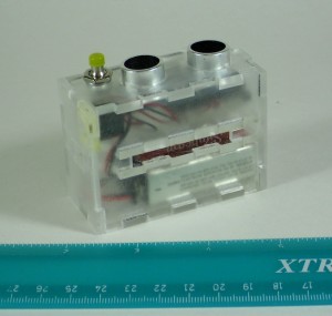
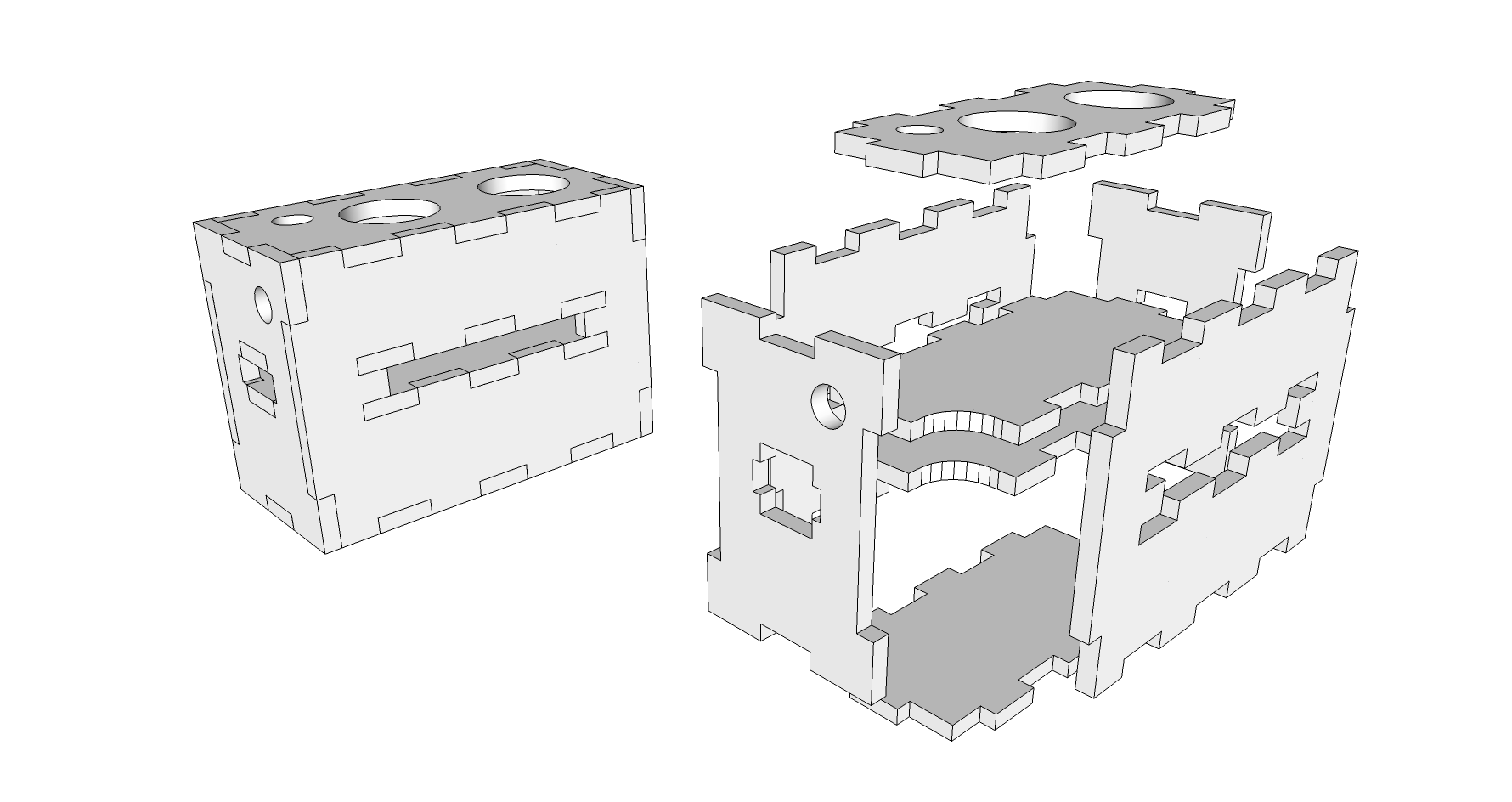 Since I belong to the local Makerspace, and we have a nifty laser cutter, it’s no surprise I did an acrylic case for my project. The design is in Sketchup, and based on 3 mm or 1/8 inch acrylic (you can download the Sketchup sonareye-acrylic.zip from here). It’s unusual in that I wanted a convenient way to hold the parts, but I also wanted it to be sturdy. For that reason, I separated the battery from the sensor and added a slot for straps in between them. By allowing straps from all four sides, it gave more mounting options; plus by placing the slot higher up, the case itself acted as a support, preventing the straps from pulling the back off (which would likely happen if I just added a loop on the back).
In actual use, you’d prefit the pieces and then glue together all but the two pieces with round holes, that is, the top sensor piece and the speaker side. Once the electronics are mounted to the top piece, you could tape or glue that, and then tape the side panel so you can get inside to replace the battery from time to time. I used a small piece of double-sided foam tape to mount the speaker to the case, making sure the center hole lined up with the case’s hole for maximum volume.
For my project, everything fit surprisingly snug, but more than likely you’ll get a bit of rattle. To solve that, find some pieces of foam and carve them with a knife to ‘lock in’ the electronics pieces so they wouldn’t shift or rub. More foam can go into the battery section to keep it from rattling as well.
Conclusion
This project has been very satisfying for me, and I hope you’ll enjoy making it too. Besides a chance to try out programming a Pro Mini, and opening up ideas for your own battery-powered projects, it also gives you a device that can be handy for others. In talking with a blind friend, he pointed out that while most blind people do not need this kind of device, those older or infirm might benefit from audible assistance when walking around, especially in unfamiliar surroundings. Give it a try, and you’ll think of even more uses for it yourself.
Hello, I am desperate to get my hands on one of these gizmos! I recently lost all my site having been partially sighted for many years. I have a guide dog that I’m facing great difficulties adapting. I need to locate bus stops/beans/doorways etc. So, I have two questions for you… firstly, do you make these for people? I have asked my friends, but can find no one who feels up to the task. Secondly, I notice you mentioned the latest version of the device
“chicken”clicks, I must say that for me vibration would be far superior as I am often in a noisy environment, traffic etc… I would, of course, only be too delighted to pay you if you would make me one! The only, premade, version that I can find is called the mini guide and costs upwards of €500! I cannot afford that, but, also, I cannot stand the exploitation involved with such a cost. So, I have my fingers crossed and hope, at least, to hear from you even if your answer is no. Perhaps, you will know of someone who does make these devices? Thank you so much for all your work on this project, SandyrUnfortunately, I haven’t the ability to manufacture these, either as a business (need capital) or individually (not enough time). Hopefully, someone can put one together for you eventually. My apologies.
As for vibration, I did an earlier design that incorporated a vibration motor at https://www.utopiamechanicus.com/article/sonareye-sonar-detector-for-blind/ – I found the power requirements for the motor were a bit high, and the vibration was hard to pick out (the inertia of the motor made it difficult to slow down/speed up quickly enough in response to moving the sensor around). However, the design and code is there if you wish to view it.
I am new to this arduino world….i actually got a project to make to help the visually impaired for my university practicals………can you tell me how to program an arduino mini pro with my pc………is there an application or software we have to download???
It’s similiar to the Arduino, with an extra device for USB: https://www.utopiamechanicus.com/article/working-with-arduino-pro-mini/
Alternatley, you could use a Nano, which has USB built in.
Let me get this straight are you trying to say that we have to insert two pins in one digital ground…..or can we do in seperate?
You don’t have to – just wire +5v and Ground as usual – I did this so the sonar board can be soldered directly to the pro mini.
My cousin recently became blind due to a rare disease. The local community college (eac.edu) is starting a FAB LAB. I plan on taking some arduino pro mini’s and nano’s to their FAB LAB and see if some students will make this project for me. I already have the walking sticks to attach the device to. I have all the other components also. Thanks for your contribution.