
While working with my design for the Braille display, I’ve been well aware that others will wonder why I’ve made these particular choices.
The main reasons: cost and complexity (which usually means cost!)
There are other possible Braille Display ideas; and like others, I went through the designs, tweaking them with my own ideas. However, each had problems when considered from an ultra-low-cost standpoint.
Of course, the first design I tried was using solenoids to move individual pins up and down. However, solenoids are power hungry, and they would have to be custom made – and since the typical Braille character is about 2.5mm between dots (center to center), the tolerances are very tight. Finally, the driver circuit for a solenoid version would need to be much more robust – after all, activating a 40 character display would mean driving as many as 200-300 little magnetic solenoids, one for each pin! While there are ways to solve these problems, it became apparent that as a first device, it would be too complicated for others to make.
It didn’t take long until I realized that molded Braille dots on the edge of a disk would work well, and that showing half of the Braille character on each disk would keep complexity down while staying compact. Rotating the disks would show any character possible in Braille, and so the machine simply rotated half characters to a touch window at the top (side note: after patting myself on the back for such an innovative design, a couple of readers steered me to the Natesan Braille Display, which has been in development for several years).
The problem with this design? Again, looking at the very small tolerances of display, the disks would be about 3.5mm wide, maximum. And, since the disk’s edge already shows the Braille half characters, where does the drive gear go? One possibility was to turn the disk into a dot/gear combination (2mm of the disk edge for raised dots, 1.5mm for recessed gear teeth, for example). However, you go from tight to very tight tolerances, and the project ceases to be simple to design. Also, you still need to drive those gears, and that means either a motor per wheel (high power/expensive), or a motor moving between wheels, and yet somehow engaging each gear as it moved along. To do this, the recessed gear of each disk had to be brought out with a second gear, and then the motor’s gear had to selectively engage with each in turn.
In fact, it was this disk idea that led to the current version: while trying to come up with ways to drive each disk, I though of small 1mm racks that engaged each disk’s gear; then, a motor moved along, moving each rack in turn and at the same time driving (rotating) the disks. And that was my ‘aha’ moment – since I was moving the racks anyway, why not print the Braille dots on them, and skip the disks entirely!
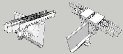
From there, the design moved rapidly – using racks for the Braille characters, a motor moved underneath and engaged each individually, moving it forward/backward to position under a touch window. In turn, another motor moved that motor assembly left and right, to engage each rack in turn.
The final problem was how to keep racks in place after the motor had moved on. This piece of the puzzle was, simply put, Divine Intervention: it appeared fully formed in my brain one day, so much so I cannot in good conscience take credit for it. By pulling a ridge in line with the motor as the device moved, this ridge engaged in the underside of each rack between its teeth, locking the gear in place and preventing movement. By shaping it properly, The ridge engaged with each rack with low friction, and yet prevented forward/backward motion of each rack. A slot was cut out in the ridge for the motor’s toothed gear – as the ridge moved, the tooth slipped into each rack in turn between teeth, moved the appropriate rod/rack to the right position, and then moved to the next.
That’s the design – and unlike the others, very simple and low cost. An Arduino seems to be sufficient to drive it, two stepper motors are enough, and minimal parts needed besides the actual rods/racking.
But this is just the start; from here, there’s countless variations possible:
- The current motor design is meant for tinkering, and so it was moved into a separate section in the design. In the final device, both motors will fit in the main section underneath the racks.
- The ridge needs to be in contact constantly no matter the rack drive motor’s position, so it needs to be at a minimum about two times the width of the display – so for a 40 character device it will be about 80cm (32inches) long. However, the ridge could be replaced with a flexible spring, belt, or chain that loops under the motors; this way, it would lock the racks at the top, and engage with the left/right motor at the bottom of the ‘loop’ for motion.
- The gear is currently huge, and designed to move one character along per tooth movement. Obviously, as I debug the drive controls, I can move to a smaller gear (and more/smaller teeth on the rack’s underside of each Braille stick).
- Multiple motors. Right now, there is a single motor to move all racks, meaning one character at a time can move. However, imagine an 80-character device (=160 Braille rods/racks): obviously the time to display is slower. But add 7 more motor to move racks, space them evenly along the ridge, and you have almost the speed of a 10-character device, since they can move in parallel. The complexity will change (hopefully the Arduino can handle it, and a new driver board will definitely need to be constructed!), but this would be a faster option for those willing to spend the extra money.
- Each rack can be shortened. Right now, each Braille position uses about 12mm/0.5 inch of space along the rod. Add a bit more space for the ends, and each rod is about 8 inches long. The reason for this was to provide standard space above/below each character for touch. If, after testing with the Blind, it’s possible to reduce this character height, then the rods can be shortened. The result is a much smaller device, since right now the device length (depth) is roughly twice the length of each rod. What’s the ultimate limit? It depends on what users decide, but if they can be packed in tightly, it’s possible to reduce the rod to a display size of under 2 inches for a 4×2 (computer) Braille display! Here’s how: take all 16 possibly 4-bit patterns, and overlap them carefully, resulting in a design with each of the 16 possible patterns in a 16 bit ‘string’ (note: I mention 16 instead of 8 because I was originally anticipating ‘computer’ Braille, which uses a 4×2 cell instead of 3×2, and adds space for control characters, etc). Turning this into a Braille dot/no dot design, it looks like this (with ‘O’ representing a raised dot, and ‘-‘ as a blank spot):
O O - - O - - - - O O O O - O - O O -Try it out – you’ll see that as you move along, every single 4-bit pattern is represented here (note the extra three spots at the end are just to flesh out the patterns so the last ones have a full 4 spots). The result is the rack only needs to move one dot place to get to the next pattern (about 2.5mm). Taken together, it means that if this design can truly be packed and is readable by the Blind, then the rod design can go from 8inches/20cm down to about 2.5mm x 19, or about 4.8cm (1.9inch), which opens up the possibility of multi-row displays…
I hope this explains my design decisions, and that, although I’m happy with my current design, it’s not meant to be the final word. However, you likely noticed that each improvement means more cost, or more complexity. Both of these have been ‘bad’ words during my work on this design: complexity and cost means fewer people can make this device, and the goal is first and foremost to get simple, low-cost designs out there ASAP.
And once they are out there, then other designs can appear, giving users everywhere choices, based on the cost/complexity tradeoffs they want.
you have not mentioned about racks going to their initial position after character is displayed. How can we achieve this mechanism??